
FRAME DESIGN OF ENGINE MOUNT
Overview: Frame construction is used throughout the aerospace industry in the creation of welded steel-tube fuselages, piston-engine motor mounts, ribs and landing gear. In this activity, I design a frame assembly for a motor mount structure for a Lycoming 0-300 to be installed in a light aircraft
Procedure: The frame must meet the constraints below
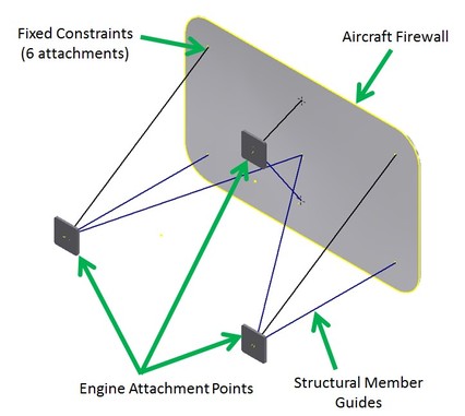
- The large plate represents the aircraft firewall as shown in the image below. This must be grounded as the stable part of the frame. Used fixed constraints on the six firewall to structural member attachment point
- The structure will support one Lycoming 0-300 engine (250 lbs) attached at the three points indicated
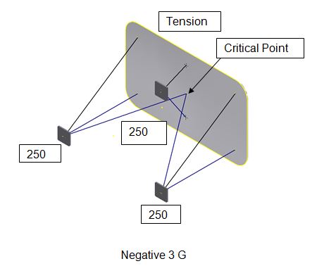
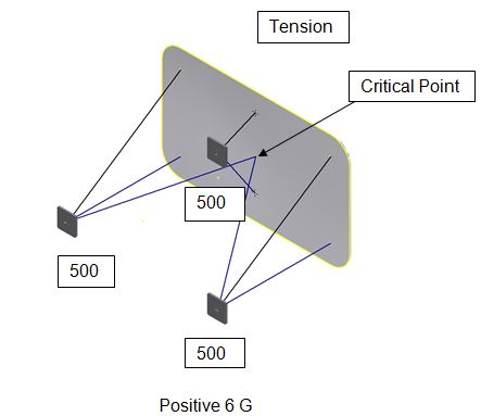
- The structure will be loaded with negative 3 G and positive 6 G which is simulated by exaggerated engine weight
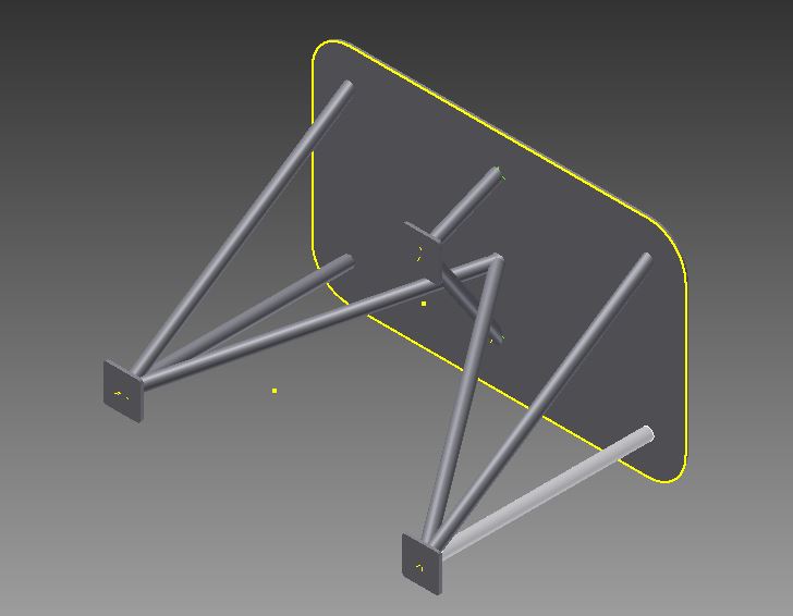
- The structural members will be 1 1/2 in. ANSI pipe.
- Frame members should be mitered as necessary
I calculated the forces that must be simulated with the positive and negative G loads. I labeled the frames below with the forces that will be modeled for each loading condition. I also labeled the structural members below as compression or tension. I predicted where the critical point will be for each loading condition.
|
|
Design: I used Autodesk Inventor to create a model of the frame design
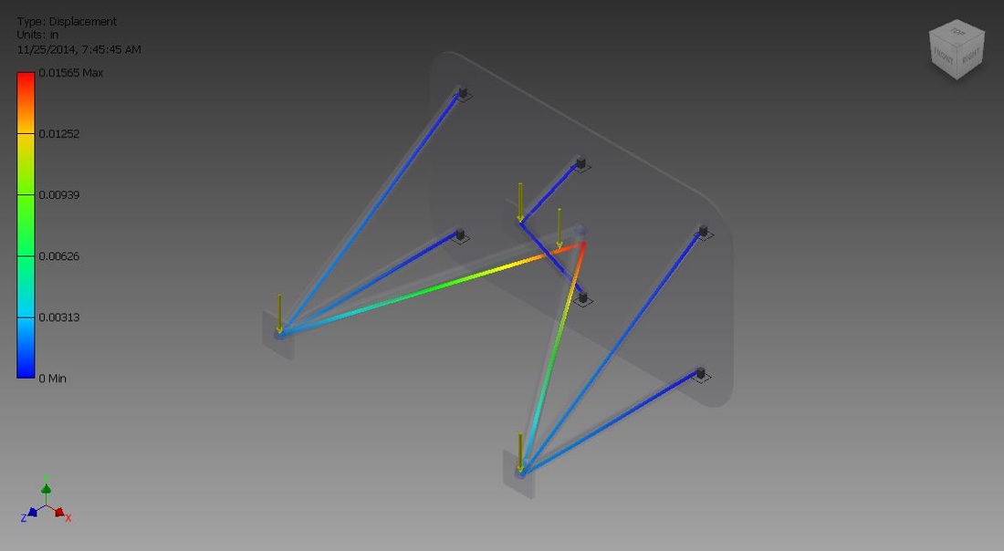
Frame Analysis
|
3G

|
6G
|
Mass of Frame=399.532 lbs
Design Benefits: The material of the frame is steel, specifically ANSI/AISC Rolled Steel and the constraints used were miter, and it was simulated during the creation process with forces of negative 3G and positive 6G. It's design and structure also make it a unique item.
Conclusion
1. Explain how the frame analysis showed that the critical area was different than the critical area that you predicted.
It showed the critical point on the center of the frame whereas I predicted it would be at the sides of the frame.
2. Explain what additional loading conditions that an aircraft designer needs to include as a constraint.
Weight, force, material, structure
